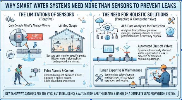
Why Smart Water Systems Need More Than Sensors to Prevent Leaks
A small water leak can cause significant damage if it goes unnoticed for several hours. In homes, commercial buildings, and industrial facilities, connected water monitoring systems are increasingly used to detect unusual conditions and alert operators before problems become more serious. However, detecting a leak is only one part of the challenge. Reliable PCB assembly solutions help support the electronic hardware that connects sensors, controllers, and automated equipment within these systems. Once a potential leak is identified, the system must decide whether to issue a warning, activate a valve, or initiate another predefined response. This makes industrial control PCBA an important part of water management equipment that needs to process sensor information and control physical devices.
Why Leak Detection Alone Is Not Enough
Traditional leak detection devices often focus on identifying the presence of water in an unexpected location.
A simple moisture sensor may trigger an alarm when water reaches its sensing electrodes. This can be useful near water heaters, washing machines, or equipment rooms.
However, detecting moisture does not necessarily prevent additional water from escaping.
If a pipe continues supplying water, the leak may worsen even after an alarm has been activated.
More advanced systems combine detection with automated responses. Depending on the installation, a controller may send a notification, close a motorized valve, or request that a pump stop operating.
These functions require coordination between sensors, electronic control circuits, and mechanical equipment.
The objective is not merely to recognize an abnormal condition, but to respond appropriately before the consequences become more severe.
Different Sensors Identify Different Water Problems
Smart water management systems may use several types of sensors because water-related problems do not always produce the same symptoms.
Moisture sensors can detect water where it should not be present. They are commonly used around appliances, storage areas, and equipment enclosures.
Flow sensors measure water movement through a pipe. Unexpected flow during periods when a system should be inactive may indicate a possible leak.
Pressure sensors provide another source of information. Changes in pressure can help identify certain abnormal operating conditions, although pressure variation alone does not confirm that a leak exists.
Water level sensors are also useful in tanks, reservoirs, and pumping installations.
For example, a level sensor may indicate that a storage tank is approaching its maximum permitted level.
Each sensor provides information about a different physical condition.
Combining these measurements can improve system awareness, but engineers must still account for normal operating variations and possible false alarms.
The Control Board Connects Detection with Action
Sensors provide measurements, but a controller determines how the system should respond.
A typical water management controller may include a microcontroller, signal conditioning circuits, power regulation components, communication interfaces, and output drivers.
The microcontroller processes incoming information according to programmed operating rules.
For example, a system may be configured to close a valve when a flow sensor detects sustained unexpected water movement under defined conditions.
In another application, a controller may activate a pump when the water level in a storage tank falls below a specified threshold.
These functions depend on the electrical characteristics of the connected equipment.
A low-power sensor input cannot directly drive every type of valve or pump. Suitable interface circuitry, relays, or motor drivers may be required.
Engineers must also consider electrical protection, isolation where necessary, and the consequences of incorrect control commands.
The control board therefore acts as the link between digital information and physical water management equipment.
Automated Valves Introduce Mechanical Challenges
A motorized valve can help limit water loss by interrupting the supply when a system detects a potentially serious problem.
However, operating a valve is more complicated than switching an indicator light on or off.
Different valve mechanisms require different electrical and mechanical control methods.
Some use electric motors, while others use solenoid actuators.
The controller must provide an appropriate drive signal and manage the operating requirements of the selected device.
Valve movement may also be affected by mechanical wear, contamination, or pressure conditions.
In some designs, position feedback helps determine whether the valve has reached its intended state.
Without feedback, a controller may know that it issued a closing command but may not be able to confirm that the valve actually closed.
This distinction is important in applications where reliable shutoff is a critical requirement.
What Happens When the Internet Connection Fails?
Many smart water monitoring products connect to mobile applications or cloud platforms.
Remote connectivity allows users to receive alerts, review operating information, and manage certain system settings.
However, internet access is not always available.
A temporary network outage should not automatically prevent essential local monitoring or control functions from operating.
For example, a water protection controller may be designed to close a valve locally when a predefined leak condition is detected, even if it cannot send a notification to the user’s phone.
This requires the necessary decision-making functions to remain available within the local system.
Engineers must also consider power interruptions, communication failures between devices, and unexpected controller resets.
The appropriate response depends on the installation and its safety requirements.
For some applications, maintaining water supply may be important. In others, stopping water flow may be the preferred response.
These decisions should be defined during system design rather than left to chance.
Industrial Water Systems Have Additional Requirements
Water management extends beyond residential leak detection.
Industrial facilities use electronic control systems to manage pumps, tanks, pipelines, cooling equipment, and process water distribution.
These installations may involve larger motors, multiple sensors, and more complex operating sequences.
For example, a cooling water system may monitor flow, pressure, and temperature while coordinating several pumps.
If abnormal conditions occur, the controller may need to generate an alarm or execute a defined equipment response.
Industrial installations also introduce electrical challenges.
Long sensor cables, switching equipment, motor drives, and grounding arrangements can influence signal quality and system behavior.
Control hardware must therefore be designed for the electrical environment and operating requirements of the installation.
Appropriate enclosure protection and environmental considerations are also important, especially when equipment is installed near water or in humid locations.
Testing the Complete Water Management System
A control board can pass its electrical tests without proving that the complete water management system will operate correctly.
Board-level verification may confirm power supply outputs, sensor inputs, communication functions, and control signals.
However, system-level testing is needed to evaluate interactions with actual sensors, valves, pumps, and other connected equipment.
For example, engineers may simulate an abnormal flow condition and verify whether the controller generates the expected response.
They may also test sensor disconnection, communication interruption, or power restoration behavior.
If valve position feedback is available, testing can confirm whether the system correctly interprets that information.
These evaluations help identify problems that may not appear when the circuit board is tested independently.
The test conditions should reflect the intended application and its defined operating requirements.
Conclusion
Smart water management systems demonstrate why sensing alone is not enough to protect equipment and property from water-related problems.
Sensors identify physical conditions, controllers interpret the information, and actuators carry out appropriate responses.
Reliable operation depends on how these elements work together.
Electronic hardware, mechanical equipment, communication systems, and control software must all be designed around the intended application.
As water monitoring becomes more connected and automated, the most useful systems will be those that can not only detect abnormal conditions but also respond predictably when they occur.

Related Posts

Arizona Real Estate News: Latest Housing Market Trends, Property Prices, and Future Opportunities

Shiesty Mask: Everything You Need to Know About Its Style, Popularity, and Everyday Use